Each construction project, whether it is a small residential house, a commercial high-rise, or an infrastructure project, always begins with a set of blueprints. Blueprints, also called construction drawings, are the industry language in the construction industry. Blueprints create a connection between the intent of the architect, the needs of the engineer, and the means of construction by contractors and builders. When a project relies on a lack of good drawings, it is almost certain to suffer from miscommunication, financial issues, delays, and difficult conversations.
This blog will explain everything you need to know about construction drawings: what they are, why they are important, types of drawings and components of each, tools used to produce drawings, and how to read drawings.
What are Construction Drawings?
Construction drawings are detailed, scaled drawings that represent the design, layout, and specifications of a building project. They turn design ideas into actionable directions for contractors, engineers, and construction workers.
Construction drawings supply specific dimensions, materials, finishes, and installation specifications and therefore ensure that all parties, including architects, engineers, contractors, project managers, and clients, have the same probable understanding of the entire project, as a form of universal communication among them all.
They truly are a ‘road map’ on how structures will get built, and they can serve as a legal document that establishes how a structure should be built.
The Importance of Construction Drawings
Construction drawings go beyond simple representations of design. Their importance is felt through every phase of a project:
Communication: Drawings provide a set of concrete examples that each person involved in the project interprets without ambiguity.
Accuracy: Drawings provide certainty, not guesswork, by including all measurements, layouts, and specifications.
Cost Control: Drawings make sure there is less waste of material, as well as reduce the chance of making a mistake that will cost the owner money during construction.
Building Compliance: Construction drawings ensure an accurate representation of the project meets building codes, safety standards, and zoning laws.
Legal Protection / Documentation: Construction drawings will form part of the contract documents; therefore, they provide protection to each party in the case of a dispute.
Construction drawings are essential. They minimize misaligned expectations, wasted resources, and increased amounts of associated risk.
Categories of Construction Drawings
Construction drawings are not universally applicable. Construction drawings are prepared based on the project phase and the level of information required. Here are some of the common types of construction drawings.
Architectural Drawings – Represent the overall design, layout, and aesthetic of the building. Architectural drawings include floor plans, elevations, and sections.
Structural Drawings – Detailing the structural system of the building, including the foundation, beams, and load-bearing structures.
Mechanical Drawings – Detailing systems such as heating, ventilation, and air conditioning (HVAC).
Electrical Drawings – Detailing electrical features, including wiring schemes, lighting schemes, and circuit diagrams.
Plumbing Drawings – Detailing the water supply, drainage and sewage system.
Landscape Drawings – Detailing above-grade elements (i.e. gardens, driveways, outdoors) of the project.
Shop Drawings – Drawings completed and submitted by a subcontractor detailing models and specific descriptions of manufactured construction items or products.
Get In Touch With Us Today For More Details
Essential Elements of Construction Drawings
Although construction drawings differ from one project to another, there are common elements found in almost every drawing.
Title Block: Whether at the bottom of the drawing or the side, the title block tells you critical information such as the project name, drawing title, date, scale, and revision information.
Scale: Drawings are reduced-scale drawings so that they can fit on paper, and appear smaller than actual size, but do represent accurate proportional relationships.
Dimensions: Accurate measurements for use in constructing the work.
Notes & Annotations: Notes and annotations that include additional instructions or clarifications that may not be clear from the drawing alone.
Symbols & Legends: Standardized icons representing materials, fixtures, or construction elements.
Grid System: Used to locate elements on expanded drawings with assigned coordinates.
These elements help create clear and consistent information across all project documentation.
Programs and Tools for Construction Drawings
Construction drawings used to be hand-drawn design pieces created with the use of a simple (and complex) tool assortment, pencil, compass, scales, and often on tracing paper. Today, construction drawings are completed with greater detail and accuracy and faster use of software.
Some of the common tools and software include,
AutoCAD – The industry standard for 2D drafting and drawing detailing.
Revit – Popular for Building Information Modelling (BIM), Revit encompasses 3Dmodellingg with construction information.
SketchUp – Typically used for conceptual and formal designs and popular amongst architects.
Bluebeam Revu -Used to review and annotate digital drawings.
Vectorworks – Providing design features and technical drawings.
Not only are the tools easier to use, but they also allow multiple collaborators to work on the same project, and the ability to design and share through online cloud options.
Construction Drawings Standards and Symbols
Construction drawings need to be standardised and use conventions so they are universally recognised and understood. Standards and conventions ensure that construction drawings are interpreted the same way regardless of who prepares the drawing and who reads the drawing.
Standards: Standards such as ANSI (American National Standards Institute) and ISO (International Organization for Standardization) offer guidance in how the drawings should be arranged.
Symbols: Symbols are used to illustrate doors, windows, electrical outlets, plumbing fixtures, and structural components. For example, a small circle with a letter in it may represent a lighting fixture, or there are dashed lines to illustrate concealed items.
Types of Lines: Solid, dashed, or dotted lines provide different information, such as the visible edge of items, concealed items, or centerlines.
Following the standards allows construction teams to avoid confusion and achieve accuracy throughout complicated projects.
Advice for Reading and Interpreting Construction Drawings
For newcomers, reading drawings can initially be daunting and difficult. However, if you follow these steps, reading and interpreting them can be simple:
Begin with the Title Block – This provides you with the basic project information, scale, and type of drawing.
Know the Scale – You’ll want to know how dimensions relate to the real world.
Review the Symbols and Legends – Refer to the legend to understand what they’re referencing if you have any symbols that you’re unfamiliar with.
Read the Floor Plan First – Before you read sections, elevations, and details, look at the floor plan to understand the layout.
Read Sections and Elevations – These drawings give you a sense of the height and depth of various aspects of the structure.
Take Jots – Mark up a copy with your own jots or questions that can get clarified later.
Eventually, due to experience, a professional will become familiar with drawing and reading. Like learning a new language, you become fluent.
Examples of Construction Drawings
Examples can show how drawings can take shape in different ways:
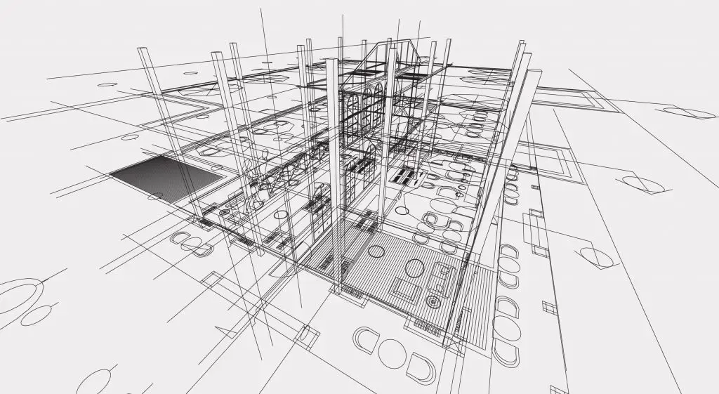
An example of a Floor Plan: Describe the organisation of rooms, walls, doors, windows on a single level of a building – mid-level zoom, looking down a shaft of light, into the building.
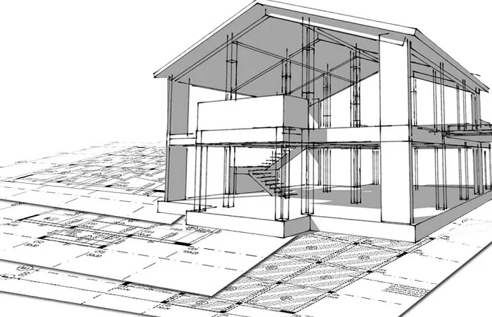
An example of an Elevation: Describe what is seen externally; i.e. height, facade, etc., also architectural style.
An example of a Section: Cut through of the building with internal characteristics such as wall thickness, stairs, structure, etc.
An example of a Detail Drawing: a close-up of an application drawing that describes a feature, such as window installation or beam connection – very, very close zoom.
These examples describe drawings that range from a greater overview to details and are supportive of the construction process in each direction of the rendering process.
Final thoughts
Construction drawings are at the heart of every successful project. They are the bridge between dreams and reality, allowing thoughts, wishes and ideas regarding buildings to develop into a real structure with accuracy and exactness. Construction drawings can take many forms, from architectural floor plans to more detailed and complicated shop drawings, but in each case, they serve to provide a common language to all parties involved.
As technology continues to evolve, drawings and our perspective upon them are changing, incorporating digital tools and BIM into our drawings. The overarching goal, however, does not change – to provide clarity, accuracy and guidance throughout the planning and construction process. For businesses, practitioners, and clients, understanding construction drawings will only enhance your success stories on your projects.
FAQs
1. What are the key objectives of construction drawings?
They provide detailed, scaled instructions to assist contractors and builders with executing a project correctly.
2. Who creates construction drawings?
Construction drawings are usually created by Architects, Engineers, and designers. Subcontractors typically create shop drawings for specific details.
3. Are construction drawings binding?
Yes, construction drawings are considered contract documents, and they can assist with contract claims and disputes.
4. What is the difference between drawings and blueprints?
Blueprints were originally created from a chemical printing process. Today, the term is commonly used to identify construction drawings; however, blueprints have been replaced by digital formats.
5. Will construction drawings be amended during the course of a project?
Yes. Changes to the construction drawings occur regularly due to site conditions, changes in client preferences or constraints, or changes in regulatory requirements. There is generally a clear labelling strategy in use for what the amended version is, so confusion can be avoided.